“In-band operation” is an operating concept for ham radio contesting meaning the use of more than one radio on the same frequency band. To prevent equipment damage and violation of contest rules this requires an interlocking system, preventing transmission by more than one radio at the time. The switch described below also implements sharing a single power amplifier by two radios.
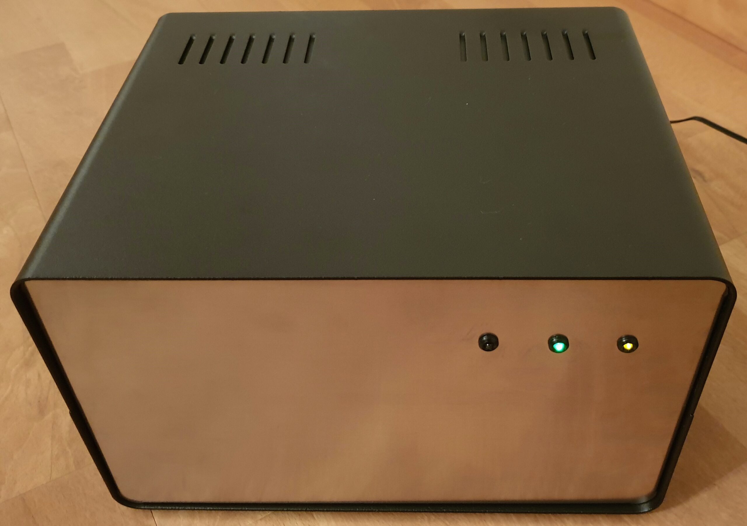
The design is based on used/military surplus components mainly found on eBay. The cabinet is a Conrad GSS10 general purpose electronics cabinet.
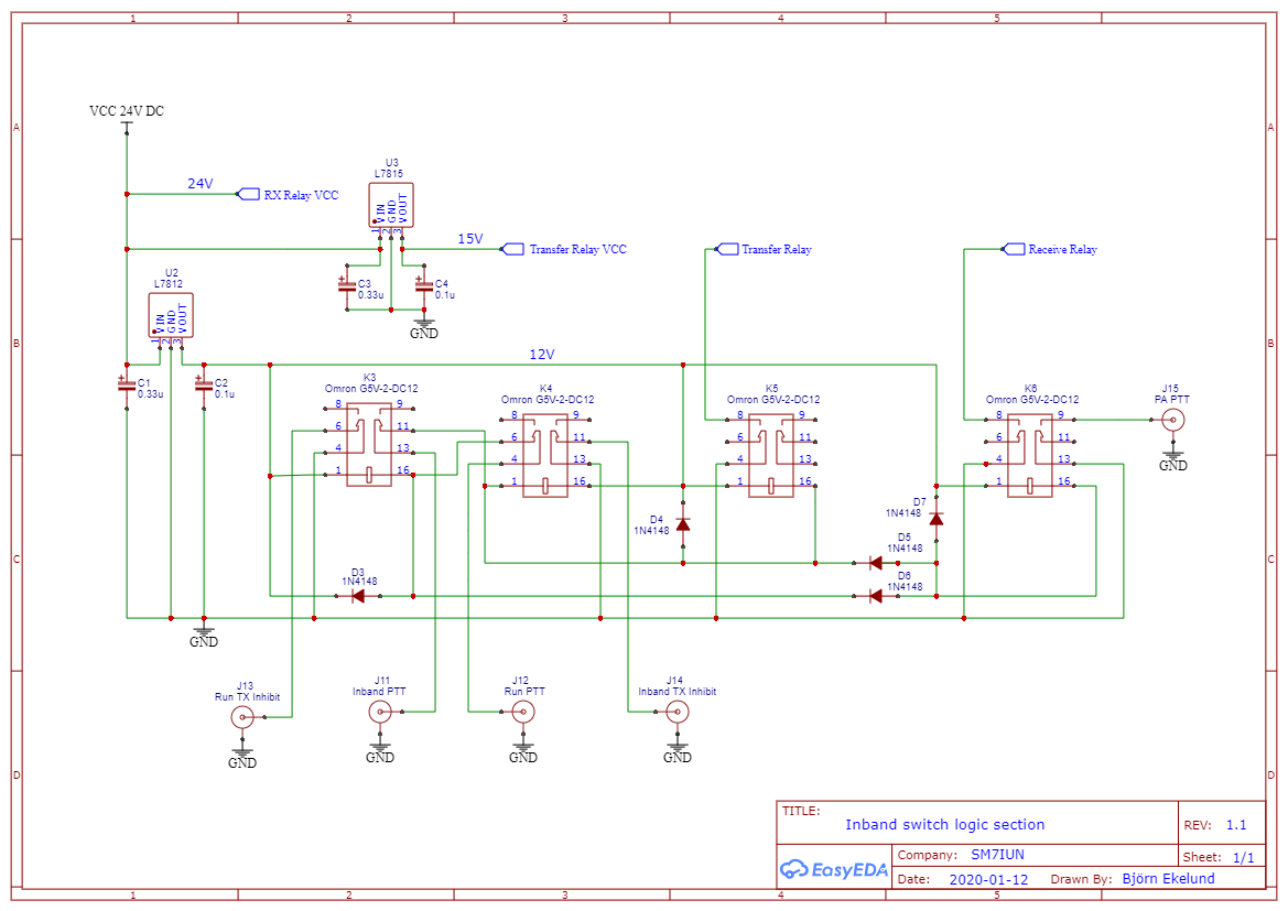
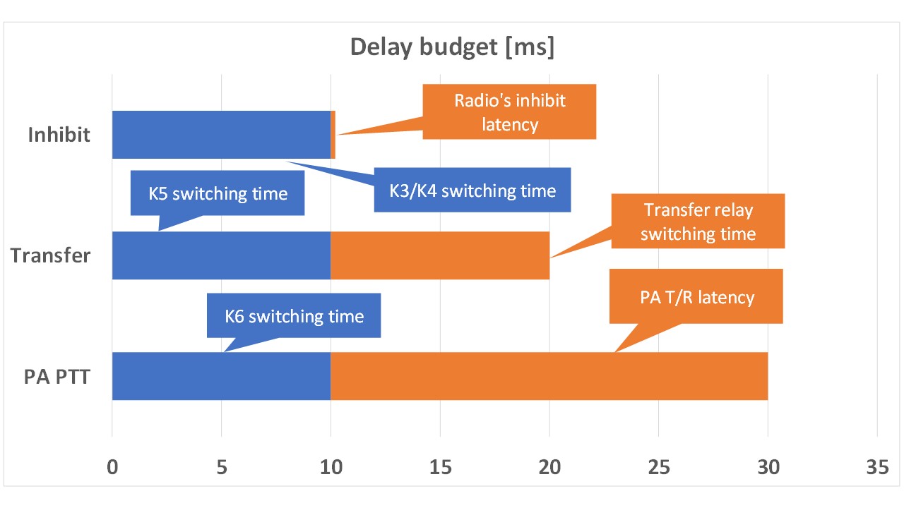
Although introducing a latency, using a relay and not a transister for the Inhibit signal is not a problem providing transmission lead time in the radio/keyer is set longer than the relay’s switching time. If your set up really requires zero Inhibit latency, switching FET transistors like 2N7000 can be used instead of relays. Please note that the two Inhibit outputs in this design are “open collector” type and thus requires an external pull-up with most radios. This solution was chosen to support both Yaesu (12V inhibit signal) and Elecraft (5V inhibit signal).
The relay logic implements a “first one wins” interlock. It should preferably be used together with a software interlock such as that available in DXLog.net or N1MM Logger+. However, with the Inband Ant/Dummy Load port connected to a dummy load and with a fail-safe (break-before-make) transfer relay K2 the switch is inherently fail safe and will never feed RF power into a receiver input or transmit more than one signal onto the band.
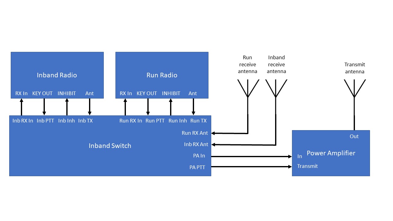
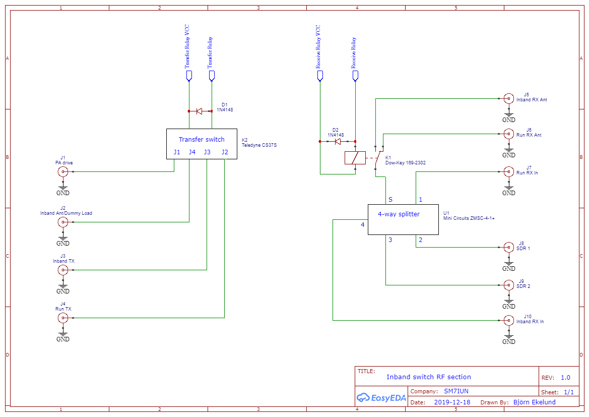
If a separate receive antenna is used for the Run radio, it should be connected to the Run RX Ant port. If the Run radio is using the same antenna for receive and transmit, the Run radio’s RX Out port should be connected to the Run RX Ant like illustrated below.

The Inband Ant/Dummy load port should normally be connected to a dummy load for protection for the unlikely case that the software interlock and/or hardware inhibit mechanics malfunctions. In the case where you want the Inband radio to always listen to the inband antenna, it should instead be connected to this port and the Inband radio’s RX Out should be connected to the Inband RX Ant port on the switch.
Using this approach, the switch is not 100% safe without the use of the inhibit signal. Without hardware inhibit, a failing software interlock may result in transmission into the inband antenna. For a passive antenna like a Yagi or dipole, this may be acceptable, but for e.g. a Beverage antenna it is normally disastrous.
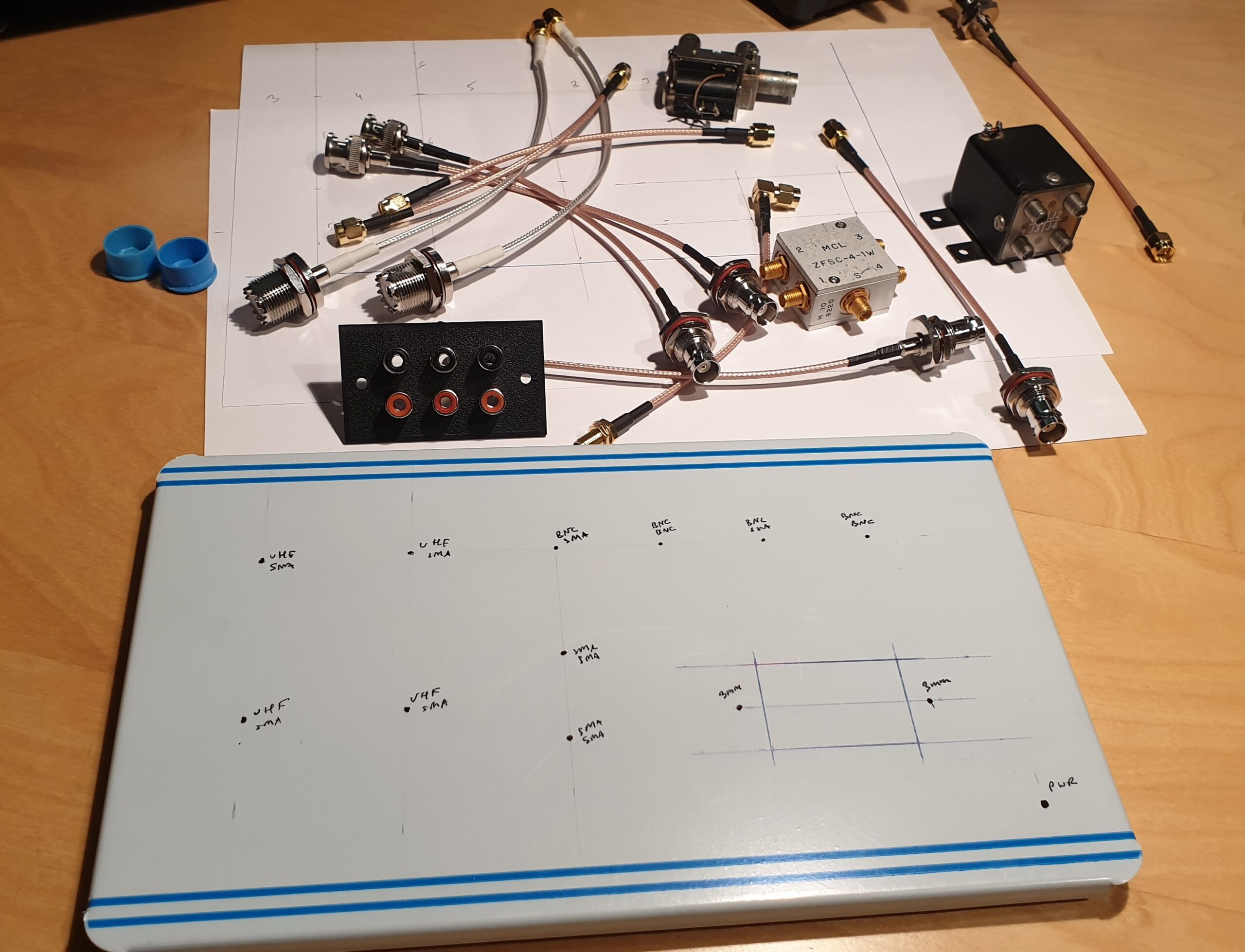

Finished pig tail cables can be found on eBay at reasonable prices. All electromechanical components are attached to cabinet using adhesive Velcro strips (Clas Ohlson carries them in convenient sheets) for easy disassembly and, perhaps most importantly, acoustic isolation. Particularly the transfer relay is quite noisy.
Further development
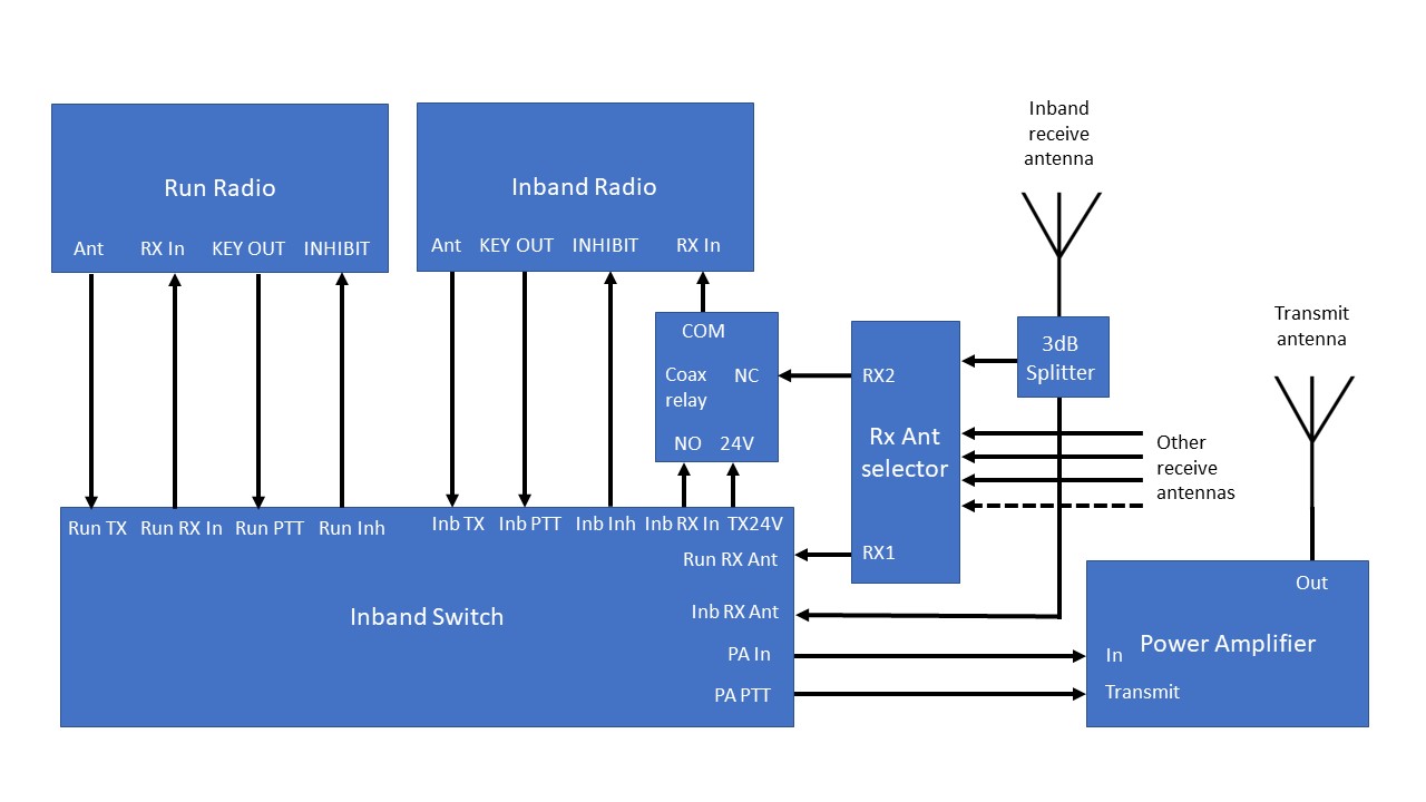
For low band operation such as the CQ 160 contest, you typically have several recevie antennas. The RemoteQTH 7ANT RX splitter is a great product for sharing multiple receive antennas between two stations. It has seven antenna inputs and two independent antenna selectors, one for each station.
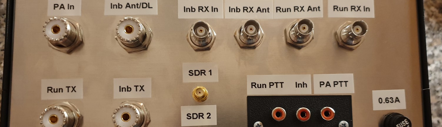
To support the use of a dual output antenna splitter, I modified the inband box, adding one more relay (in parallel with relay K6) to produce +24V on the free RCA connector in the lower right corner of the RCA jack panel. This then feeds an external coaxial relay, implementing the concept below.
An additional advantage with the concept below is that the inband antenna can be used as a receive antenna also when nobody is transmitting. To isolate the antenna from the impedance variations potentially caused by this, a MiniCircuits 3dB splitter is used. For a good inband operating experience, it is also important to have the antennas roughly similar in level. For this, adjustable attenuators or using preamps with adjustable gain is a good help.